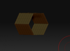
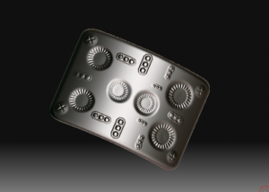
Here’s an example of using basic Zbrush building blocks. I’ve not added much detail yet, but it gives you an idea of the power of ZB’s Primitives. 100% modeled and rendered in ZB 3.12 Mac.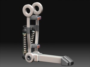
All posts by Kerwin
Zbrush Mechanical Part 4, Rounded Holes
I needed a hexagonal part with a round hole in the middle. This would seem to be a challenge for ZBrush requiring an outside modeler. However, it is actually pretty easy in ZB if you know primitives and deformers.
First, we can start with our old friend the cylinder primitive: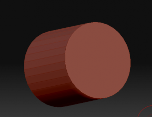
Not very hexagonal yet, and too long, but we can fix that. We tweak the number of sides to 6 and shorten the z-length in the “initialize” menu: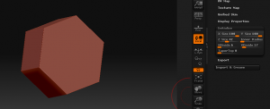
Better, but no hole . . . We can solve that by setting the “inner radius”: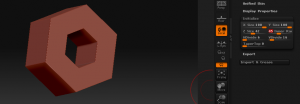
Nuts, close, but the inside whole isn’t round. I’ll need to fix that up before the boss sees it. I go ahead and make this a poly mesh and then group the inside polygons. I also divide the polymesh a few times (well, 3 actually) with the “SMT” option off (so that it doesn’t round off my hexagonal prism). Showing just the inside polygons (with display-double on for ease of viewing, I have:
Now if there was a easy way to round those off, I’d be home free. Hey, what about that “deformations” subpallet?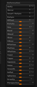
Ooo . . . I like that “RFlatten” thing . . . (It’s short for Radial Flatten). A little RFlatten and slight tweak of the size (with just X & Y turned on) and I have a nice round hole. 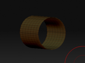
Unhiding my geometry, I’m good to go: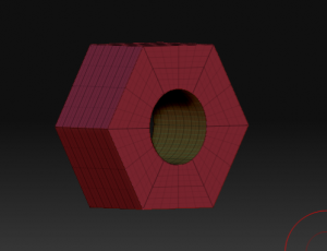
Total time to model: less than two minutes.
Zbrush Mechanical Part 3, Springing Into Action
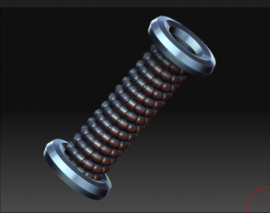
Springs are fun and a handy way to add a common mechanical detail. Zbrush has a built-in spring generator, called the helix primitive. A little setting of the initialize parameters and we get something like this:
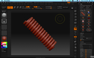
(You did know about the initialize subpallet didn’t you? If not, load up a few 3D primitives in Zbrush and look down the tools menu for the subpallet with “Initialize”. Here you can set all sorts of neat starting shapes for your primitives before making them into a polymesh.)
I didn’t make this a polymesh right away, keeping it as a helix primitive. I’m going to use a little know feature of primitives–col masking. Also, to give me some more resolution, I divided my spring a couple times by going to the geometry subpallet. (Yes, you can divide primitives the same as polymeshes!)
Inside the masking subpallet are some handy features that only work with primitives marked “col”, “row”, and “grid” with a couple mysterious slides marked “sel” and “skip”. You push any of these buttons on an unmasked primitive, nothing seems to happen and thus many a tyro is frustrated by them. This is because these buttons selective remove masks, not add them. (It feels counterintuitive to me too, but this is ZB, after all–which often feels like it was built on “opposite day” at first.)
The sel slider will choose how many adjacent rows or columns of the primitives polygon grid will be selected. The skip slider will then decide how many to skip before selecting. To get a nice box cutout, I’m going to select 3 and skip 4 which will give me a nice alternation. Now, before I go rushing to pushing the “col” button, I do the all important first step–I hit the “mask all” button on the masking subpallet. A press of the magic col button and I have a nice ring mask on my spring:
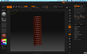
With my plain-jane spring now nicely masked, I can use “inflate” under the deformations subpallet to pull in the unmasked parts to give some additional texture. A little fiddling, and I have something like this:
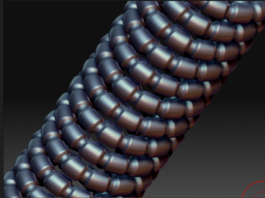
Add a couple of creative cylinders, and I have this:
Zbrush Mechanical Part 2, Spinning in Circles
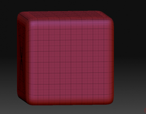
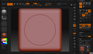
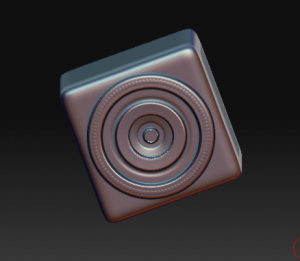
Making perfect circles is pretty important to creating the illusion of mechanical things. Fortunately there are lots of ways to do this, such as as using round alphas, but did you know you could quickly paint circular displacements right on to any hires geometry? It’s called radial symmetry and it’s really quite simple to use. Just click on the “(R)” button on the transform pallet and set the number of copies of your brush you need. Set it really high (up to 100) and then you can quickly spin-up perfectly circular ridges. The clay brush will keep these ridges perfectly level. It’s a pretty easy 1-2-3.
Zbrush Mechanical Part 1, Extracting
There’s always a lot of discussion about “Can you do mechanical modeling in Zbrush?” The answer from one camp is “No, the soft modeling orientation of ZB makes it too hard. . . .” Another camp will say, “But look at the results some guys like Meats Meier can get!”
The answer, as with lots of things in life, lies somewhere in between. ZBrush requires you to think about your mechanical models as if you'[re working with clay. This means that you need to think of your tools as being built up from things that already have structure, like platonic forms of cubes, cylinders, cones, etc. Often the trick is to start with something that has approximately the right shape and work to refine from there.
For example, I wanted to make a curved plate. I realized the plate was really a segment of a cylinder. After create a Cylinder from Zbrush’s primitives, I turned it into a polymesh (with the “Make Polymsh3d” button). Them I hid all the geometry of cylinder other than the curved segment that represented my plate. Fortunately the edges were going to be roughly square as is ZBrush’s selection
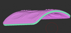
tool. With just the mesh I wanted to be the basis for my plate visible, I went to the Subtools sub-pallet of the tools menu, and used the big “Extract” button. In one step, the visible shape was extracted and given thickness. (The sliders next to the Extract button will let you play with smoothness and thickness to your liking.) Even better the front back and the edge of the plate all had new subgroups! Neat!
For the plate in the illustration, I just used some alphas I had to decorate after subdividing the mesh to a fine detail. Codeman Studios makes a nice set of Alphas if you’re looking for a profesional set, but there are pleanty to choose from on the web. For applying the alphas, I used the drag-dot brush and turned on X and Z symmetry as needed. To ensure my symmetry was good, I used the “S. Pivot” command to set the pivot to the center of the mesh. (S. Pivot works by hiding everything but central mass of an object and it will move the pivot to the geometric center of what is visible.)
Sculpted Prims in Modo, Part III
Here’s an experimental kangaroo head using only 1 prim. with my current techniques.
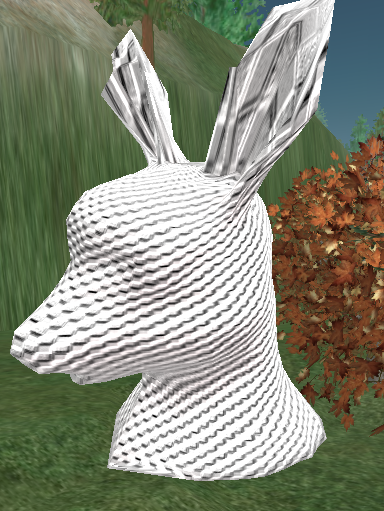
I’m really stretching the geometry by including his ears in the same Prim, but you get the idea. This is powerful stuff for Avatar modeling!
Sculpted Prims in Modo, Part II
So here’s the testbed:
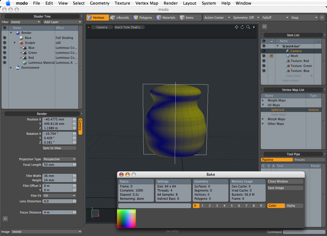
http://www.rabbitroo.com/SL/SLtest4.lxo
To use this testbed in Modo to make your own Sculpted Prims, you need to do the following steps:
1) Delete my test mesh and paste in your own mesh object.
2) Create a spherical map or cylindrical map wrapped around the Y axis. Make sure the map fills the UV space nicely–it should fill the space corner to corner. Sometimes “capping” tesslated spheres at the top (e.g. beveling the pole points) will make the spherical map lie flat correctly.
3) Make sure your object has the default texture. If not, adjust surfaces accordingly.
4) Autosize the Red, Green, and Blue texture locator’s. This will squish your object into cubic proportions, but you can stretch this out again in SL. I’ve found you usually get better geometry if you more evenly distributed the displacement data. If you really need to maintain proportions when baking, try to make the texture locator’s fit a perfect cube’s dimensions and try to center the object in that cube.
5) From the Render Menu, Bake the texture onto the UV Map created in Step 2. Save the 64×64 pixel image and load into SL.
If something goes wrong, try moving the object so that it is not intersected by any of the axis planes. Make sure no new lights or environments are added to the scene. The scene should be 100% dark except for the Sculpy textures in the testbed.
Sculpted Prims in Modo
I’ve been pretty busy puzzling out the new sculpted prims in Second Life. They are a pronominal leap forward in prim shape control. Since I do a lot of my modeling in Luxology’s Modo, I’ve used it as a testbed for making sculpted shapes. With Modo 203, I’ve been able to take this:
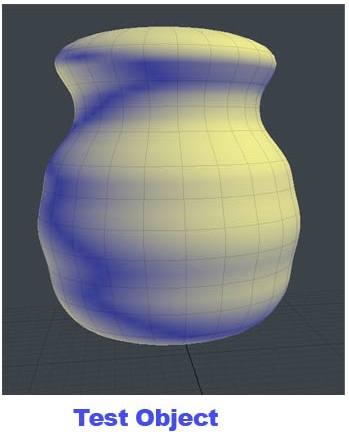
Into this in world:
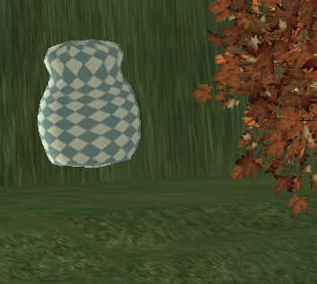
I’ll be posting my testbed and instructions in a follow-up post.

